Next: 3D Reconstruction
Up: Correspondence Analysis
Previous: Synthetic data
Real data
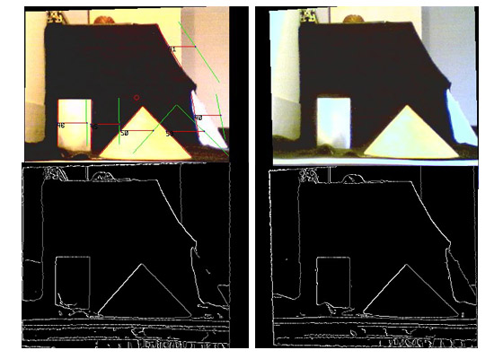
The acquisition system used was already presented in Section 3.1, now it is used to measure the accuracy of the correspondence analysis using real data. The images have to be rectified to achieve correct results. The position and size of the objects in space is known and, as in the last chapter, used to calculate the true disparities. The translation vectors are given by
 |
 |
Table 4.5 shows the true and the calculated disparities. The distance between the camera and the objects have been manually measured, thus are affected by an error which is about +/- 2cm. The maximum disparity error rises up to 5px. Which, in the case of Table 4.5, results in a deviation of 4.3 cm in the camera coordinate system. The mean disparity error is given by 2.12 px.
Next: 3D Reconstruction
Up: Correspondence Analysis
