Next: Perspective Projection
Up: Diplomarbeit
Previous: Overview
Stereo Vision
Es genügt nicht, zum Fluß zu kommenmit dem Wunsch Fische zu fangen,
man muß auch das Netz in der Hand mitnehmen.
[Chinesisches Sprichwort]
This chapter gives an overview of the mathematical background needed to understand 3D reconstruction using a stereo vision system. Section 2.1 contains information about the projection of light rays onto a sensor chip and shows the relation between the real world and the image generated at the sensor chip. An important section is on the calibration and the meaning of the intrinsic and extrinsic camera parameters. In order to gain 3D information a moving camera, a moving object or a multi-camera system is needed. To calculate 3D information in a dynamic environment, a synchronized multi-camera system is appropriate. In this thesis a two-camera system is used, the occurring geometry is explained in Section 2.3. If the geometry is known, corresponding points have to be found in order to calculate the 3D coordinates of the points. This topic is covered in Sections 2.4 and 2.5.
Stereo vision can be used in different field of applications (production line, autonomous navigating, gesture recognition [WO03] ![]()
![]() ) where depth information is needed. It is computed through triangulation, which is the base of other 3D reconstruction techniques as well.
) where depth information is needed. It is computed through triangulation, which is the base of other 3D reconstruction techniques as well.
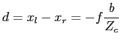
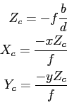
If objects are viewed from two different positions, it is possible to determine their position in 3D space as a result of their geometric relations (Equation 2.3). The process of the conversion of an image pair
in a three-dimensional representation is called stereo vision according to the spatial vision of human beings. In a static environment it is possible to obtain stereo information from one camera if its position is changing and the geometric relation between two or more taken images are known. On a mobile football playing robot without a static environment, a stereo vision system with two or more cameras has to be used in order to obtain accurate stereo information. If the images are taken at the same time, a static environment is guaranteed. The goal of a stereo analysis method is the calculation of depth information due to geometric relations. In principal every method consists of these passes [MT79]:
- Exposure
- The result of this process is mainly influenced by
the resolution of the camera sensor, the used sampling frequency
and the lighting conditions. - Camera calibration
- Determination of the intrinsic and extrinsic parameters of the
camera. - Feature extraction
- Significant features are collected. Most important is the localisation of these elements because after solving the correspondence problem, disparity is calculated as the difference of the position.
- Correspondence analysis
- Process of determining corresponding elements in the images. Different kinds of previous knowledge, constraints and plausibility considerations can be used to avoid false matches:
- Search space
- To an element in one image, the search for a corresponding element in the second image is restricted to a given window, normally the epipolar line (see Section 2.3.1 for more details about the epipolar line). Also it is assumed that the displacement of corresponding elements is limited.
- Feature properties
- If the features are distinguishable, only features with the same type (edges, corner) and the same properties (color, length) will be related to each other.
- Order constraint
- If a correspondence is found, the plausibility of other correspondences changes. Rules for such interactions are:
- Uniqueness and Integrity: Every element in the left image, has exactly one corresponding element in the right image. A special case is monocular occlusion and transparency.
- Ordering: If a correspondence

 is found, then elements which are situated on the right hand side of
  should correspond to elements on the right hand side of
  . The assumption in this case is that neighbouring elements are likely to have similar disparities.
- Scale space
- The complexity of the correspondence analysis grows with the number of elements, thus often a image pyramid is used and the search starts with the highest level (lowest resolution) of the pyramid. Are the correspondences between the few elements found the search continuous with the next lower level.
- Depth values calculation
- If the corresponding elements and the geometry of the camera is
known, depth values for the extracted features can be found.
The difference in ![]()
![]() and
and ![]() direction between two corresponding elements is called disparity. There are different kinds of disparities that can occur, namely point disparity, point and attitude disparity, gray value disparity, photometric disparity and monocular occlusion. Figure 2.1 shows an example of each case. The different disparities can be described in more detail:
direction between two corresponding elements is called disparity. There are different kinds of disparities that can occur, namely point disparity, point and attitude disparity, gray value disparity, photometric disparity and monocular occlusion. Figure 2.1 shows an example of each case. The different disparities can be described in more detail:
- a. Point disparity
- A point which is shifted in vertical and/or horizontal direction. If parallel camera axes are used, only horizontal disparities occur. If camera axes converge points with horizontal and/or vertical disparities can occur, but also points without disparity. The set of points in space that are projected without disparity is called the theoretical horopter [Mal00].
- b. Point and attitude disparities
- A beveled line in space is normally projected with different pitches.
- c. Gray value disparities
- Often points can not be compared directly, because too many ambiguities would occur, thus sets of points are compared
- d. Photometric disparities
- On glossy surfaces, a unique point can send out different amounts of light if the viewing position changes. This kind of disparity occurs due to the reflection properties of the surface and not due to the geometry. Equation 2.1 does only cover disparities which results from geometry (except occlusions).
- e. Monocular occlusions
- Areas which are near an edge are often only seen by one camera and thus no corresponding element is available in the second image.
Let
![]()
![]() and
and
![]()
![]() be the left and right image. If there are no monocular occlusions the correspondence problem can be written as
be the left and right image. If there are no monocular occlusions the correspondence problem can be written as
horizontal disparities. In the case of converge camera-axis
the horizontal and vertical disparities. The equation above only
includes a special case of stereo vision. Some more problems are:
- Occlusion
- The constraint of a totally visible surface for
both eyes is rather special hence

 is not
continuous. - Transparency
- If the surface is transparent one point of

 corresponds with more points of

 or
or
vice versa. - Photometric effects
- Caused by reflections and not due to
the geometry
Let us assume that ![]()
![]() are corresponding points of the left
are corresponding points of the left
and right image, respectively. Disparity ![]()
![]() can be calculated as
can be calculated as
- Perspective Projection
- Camera Calibration
- Stereo Geometry
- Correspondence Analysis
- 3D Reconstruction
- Summary
Next: Perspective Projection
Up: Diplomarbeit