Next: Image Acquisition
Up: Diplomarbeit
Previous: Summary
Methods
So eine Arbeit wird eigentlich nie fertig,man muß sie für fertig erklären,
wenn man nach Zeit und Umständen das Mögliche getan hat.
[Johann Wolfgang von Goethe, Italienische Reise].
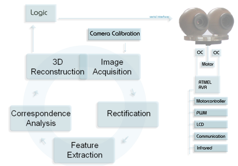
This chapter explains the methods used to reach the final result. Figure 3.1 depicts the basic process cycle of stereo reconstruction and shows where a connection between the process and a logic module (LM) can be established. The chapter is built-on as the process cycle. First of all the acquisition system is presented. Because the inner- and outer camera geometry is a priori not known, the cameras have to be calibrated. Fortunately, this has to be done only once if the camera system remains untouched and the world coordinate system is always the same. For every coordinate system used which is different from the camera coordinate system, the extrinsic parameters have to be computed, in other words, the relation between the camera and the desired world coordinate system has to be described. The intrinsic parameters should be calculated, if an intrinsic property of the camera changes (e.g. zoom will result in a change of the effective focal length). When the images are in memory, they have to be rectified in order to get rid of epipolar geometry. After rectification the epipolar line of a point ![]() corresponds to a horizontal line
corresponds to a horizontal line ![]() , where
, where ![]() is the y coordinate of the line. After the feature extraction, corresponding elements are searched and for all accordances the 3D position is computed and visualized.
is the y coordinate of the line. After the feature extraction, corresponding elements are searched and for all accordances the 3D position is computed and visualized.
After the reconstruction, the robot knows the 3D position3.1 of objects found. In relation to a dense disparity map, in which for every pixel its 3D information is stored, the 3D representation of straight lines (e.g. the start and end point) or objects is a memory efficient description. During this processing stage, the information should be transferred to the LM of the robot, where it can be used as knowledge base for basic movement decisions (e.g. as a result of obstacle avoidance [MCTM05], ball detection, goal detection,![]() ), as well as more complicated ones. For example information retrieval through self-localization [PVK05] or strategy considerations.
), as well as more complicated ones. For example information retrieval through self-localization [PVK05] or strategy considerations.
The acquisition system used consists of two customary webcams that are connected to a computer. The program that processes the stereo images is written using C and C++. The open source computer vision library [OCV] from INTEL provides a code library that is currently used to capture and rectify the images. Also, the Canny edge detector is implemented, as well as some useful data structures.
To analyse the demands and possibilities of a robot, especially in the electrical engineering domain, a connection between an ATMEL microcontroller and a computer, where the image processing is done, has been established. Via the serial (RS232) interface the computer can communicate with the controller and vice versa. A motor controller chip (L293D) is used to trigger a DC motor, which is responsible for the movement of the head. Actually, the head has only one degree of freedom, but the motor controller would be able to trigger two motors, thus the system could easily be extended to a robot-head with two degrees of freedom.
- Image Acquisition
- Calibration
- Edge detection
- Line Extraction
- Correspondence Analysis
- 3D Reconstruction and Visualization
- Robot Head
- Summary
Next: Image Acquisition
Up: Diplomarbeit

